
Making a Statetable out of it is not so difficult and it would look like this: The information for creating our Sequential Circuit is given to us by this Statediagram: But, because we will use JK Flip Flops we will have to make a bigger Statetable this time that contains also informations for each and every JK Flip Flop in our Circuit! It's pretty easy to create a Statetable out of a Statediagram. So, let's get started! Statetable from Statediagram: To make things more interesting I will this time create a Sequential Circuit having a State Diagram, finding a State Table out of it, then finding the Boolean Expressions/Functions that are needed for the State "Variables"/ JK Flip Flops and the Output and lastly create our Circuit. That's exactly how we will fill our Statetable!
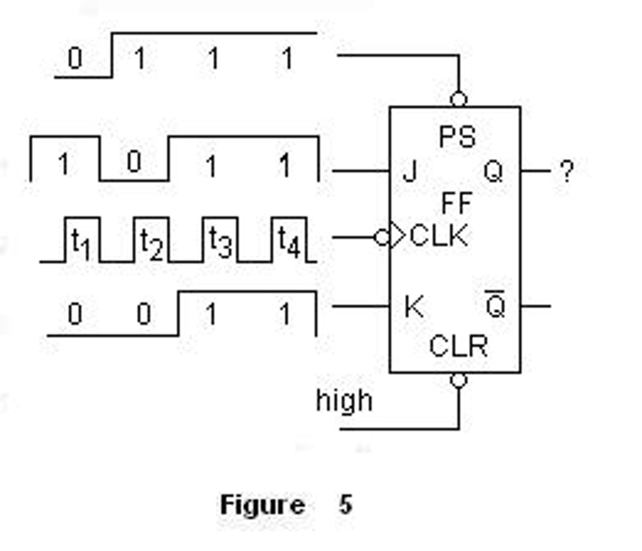
When we transition from '1' to '0' then J, K = X, 1. When we transition from '0' to '1' then J, K = 1, X. So, you have to remember (or keep somewhere) the following: J = 1, K = 0, where the next Outputs/State will be '1'īut, we will not fill our Statetable using those Cases, but with some that contain Don't Cares!. J = 0, K = 1, where the next Output/State will be '0'. J = K = 1, called Switch, where it inverses the Output/State. J = K = 0, called Memory State, where it keeps it's previous Output/State. If you remember from Flip Flops a JK Flip Flop has 4 Cases. Also, before starting out I want to point out some Tricks with which we will fill our Statetable. To make the post easier to understand and much more compact we will implement a specific Example Circuit, and we will get very in depth. :D So, withour further do let's get straight into it! That's what we will do today, and that's why I call it Advanced Sequential Circuits. We already did a good little Sequential Circuit in Sequential Circuits and in the Statetable Simplification Method, but I didn't showed you how you implement such a Circuit using JK Flip Flops instead of D Flip Flops. Unlike the Master-Slave design, which needs a complete pulse, you can also build an edge-triggered design that triggers from a rising edge ↑ or a falling edge ↓.Hello my friends it's me drifter1! Today's post will be about the implementation of an Sequential Circuit in Multisim. That’s why this configuration is called pulse-triggered JK Flip-Flop. So this circuit requires a complete pulse (0→1 →0) in order to change the output. 
Once the clock signal produces a falling edge ↓, a change from 1 to 0 (1→0), it triggers the slave section, causing the Q output to reflect the master’s output value. These signals are connected to the slave section, but this doesn’t trigger on the rising edge because the clock has been inverted. As a result, the value of the outputs in this section changes. As soon as the clock makes a rising edge ↑, which is a change from 0 to 1 (0→1), it triggers the master section.


 0 kommentar(er)
